Description
The V1000 series is in the process of being discontinued. We advise customers to upgrade to the GA500 series equivalent. Please contact our sales team for more information on transitioning from the V1000 to GA500.
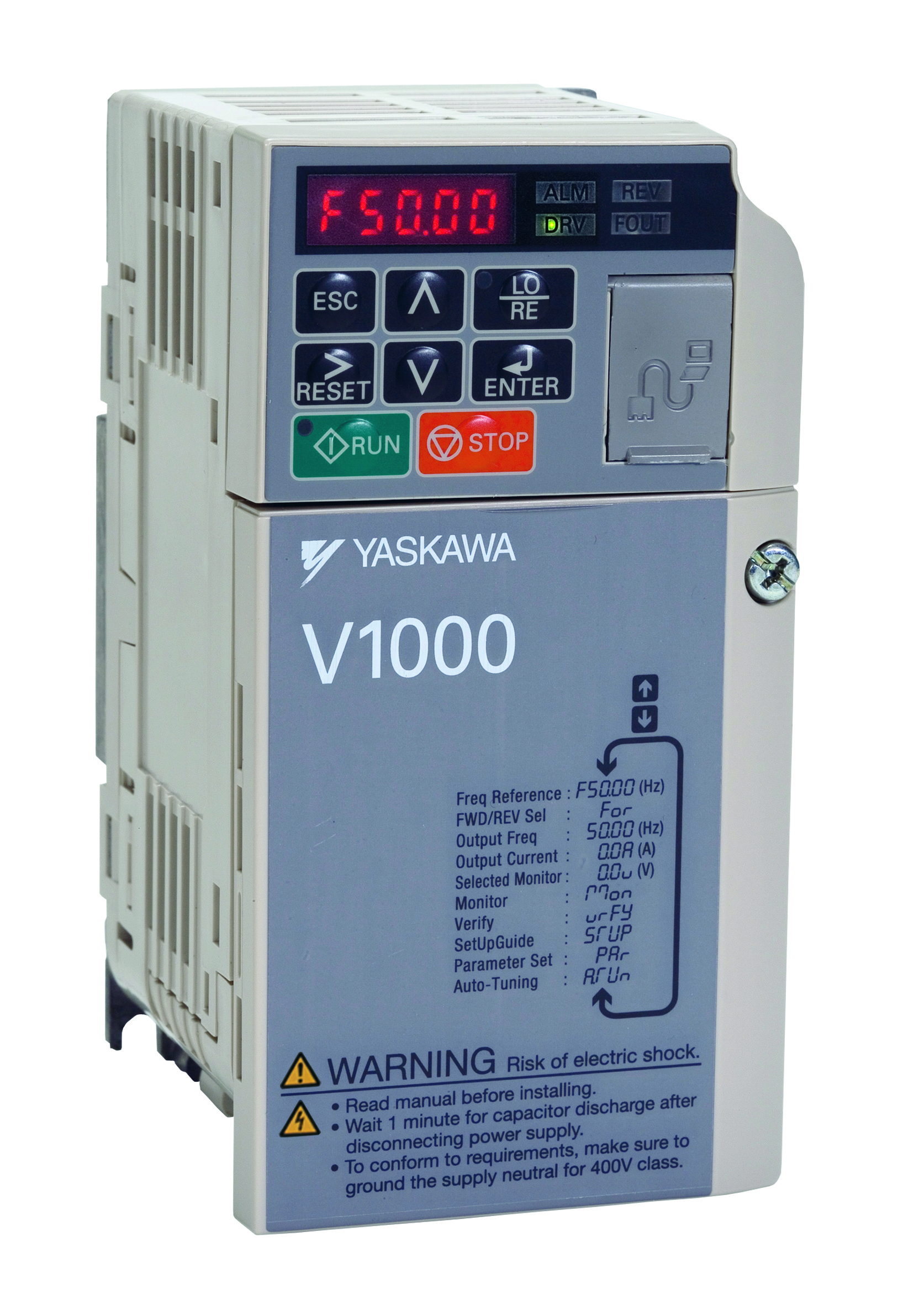
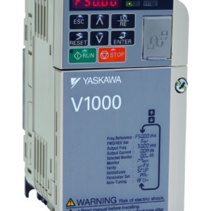
The Yaskawa V1000 variable speed AC inverter drive is a general purpose inverter with open loop vector control utilising cutting-edge motor control technology to give great performance and flexibility and making it suitable for a wide variety of applications. The advanced design of the V1000 series variable speed drive (VSD) enables it to give outstanding motor speed control. The VCBA line is designed to run on a 200 V, single phase (1ph) line.
More information about Yaskawa V1000 Inverters can be found here: V1000 Brochure
Goodwin Electronics also offers installation and panel design options for V1000 inverters, for more information on this service please feel free to contact us here: Contact Us
| Model Number | CIMR-VCBA0010BAA | |
| Voltage Class | 200 V | |
| Output | Motor Output (kW) Normal Duty | 2.2 |
| Motor Output (kW) Heavy Duty | 1.1 | |
| Rated Output (A) Normal Duty | 9.6 | |
| Rated Output (A) Heavy Duty | 8.0 | |
| Rated Output Power (kVA) Normal Duty | 3.7 | |
| Rated Output Power (kVA) Heavy Duty | 3.0 | |
| Max. Output Voltage | Three-phase 200 to 240 V (relative to input voltage) | |
| Max. Output Frequency | 400 Hz | |
| Input | Rated Input Voltage | Three Phase 200 to 240 V +10% / -15% |
| Rated Input Frequency | 50 / 60 Hz, ±5% | |
| Control Methods | Open Loop Vector Control (Current Vector), V/f Control, PM Open Loop Vector Control (for SPM and IPM motors) |
| Frequency Control Range | 0.01 to 400 Hz |
| Frequency Accuracy | Digital Input: ±0.01% of the Max. Output Freq. (-10°c to +50°c) |
| Analog Input: ±0.05% of the Max. Output Freq. (25°c ±10°c) | |
| Frequency Setting Resolution | Digital Input: 0.01 Hz |
| Analog Input: 1/1000 of Max. Freq. | |
| Output Frequency Resolution | 20 bit of maximum output frequency |
| Frequency Setting Resolution | Main Frequency reference: 0…10 V (20 kΩ) 10 bit, 4…20 mA (250 Ω) or 0…20 mA (250 Ω) 9-bit Main speed reference: Pulse train input (max. 32 kHz) |
| Starting Torque | 200% / 0.5 Hz (assumes heavy duty rated AC motor of 3.7 kW or less using open loop vector control) 50% / 6 Hz (assumes PM open loop vector control) |
| Speed Control Range | 1:100 (open loop vector control), 1:20 to 40 V/f control, 1:10 (PM open loop vector control) |
| Speed Control Accuracy | ±0.2% in open loop vector control (25°C±10°C) |
| Speed Response | 5 Hz in open loop vector (25°C±10°C) (requires rotational auto-tuning) |
| Torque Limit | Open loop vector control allows separate settings in four quadrants |
| Acceleration/Deceleration Time | 0.0s to 6000.0s (4 selectable combinations of independent acceleration and deceleration settings) |
| Braking Torque | Short-time decel torque: Over 150% for 0.1/0.2 kW motors, over 100% for 0.4/0.75 kW motors, over 50% for 1.5 kW motors, and over 20% for 2.2 kW and larger motors (over-excitation braking/high-slip braking: approx. 40%) Continuous regen. torque: Approx. 20% (approx. 125% with dynamic braking resistor option: 10% ED, 10s, internal braking transistor) |
| V/f Characteristics | User-selected programs, V/f preset patterns possible |
| Motor Protection | Motor overheat protection based on output current |
| Momentary Overcurrent Protection | Drive stops when output current exceeds 200% of Heavy Duty Rating |
| Overload Protection | Drive stops after 60 seconds at 150% of rated duty output(at heavy duty rating) |
| Overvoltage Protection | 200 V: Stops when DC bus exceeds approx. 410 V400 V: Stops when DC bus exceeds approx 820 V |
| Undervoltage Protection | Stops when DC bus Voltage falls below the following levels:Three-phase 200 V class: approx. 190 V, single-phase 200 V class: approx. 160 V, three-phase 400 V class: approx. 380 V, three-phase 380 V class: approx. 350 V |
| Momentary Power Loss Ride-Thru | Stops after approx. 15ms (default). Parameter settings allow the drive to continue running if power loss lasts for up to approx. 2s |
| Heatsink Overheat Protection | Protection by thermistor |
| Braking Resistance Overheat Protection | Overheat sensor for braking resistor (optional ERF-type , 3% ED) |
| Stall Prevention | Separate settings allowed during acceleration, and during run. Enable/disable only during deceleration. |
| Ground Fault Protection | Protection by electronic circuit |
| Charge LED | Charge LED remains lit until DC bus has fallen below approx. 50V |
| Areas of Use | Indoors |
| Ambient Temperature | -10 to +50°c (IP20 open chassis) |
| Humidity | 95 RH% or less (no condensation) |
| Storage Temperature | -20 to +60°c (short term temperature during transportation) |
| Altitude | Max. 1000m (outpur derating of 1% per 100m above 1000m, max. 3000m) |
| Shock | 10 to <20 Hz (9.8 m/s²) max., 20 to 55 Hz (5.9m/s²) max. |
